


Study on Air Permeability and Porosity of Fabric

Selim Hossain
Department of Textile Engineering
Daffodil International University
Email: selim_1999@diu.edu.bd
INTRODUCTION
Permeability is a measure of the ability of a porous material to transmit fluids. It is an important property of technical textiles particularly in protective applications, such as auto and wearable airbags where even the low permeability of the fabric can extend the interactive time in impact. Limited permeability of parachute fabric can stabilise its descent, as shown in Figure: 1
 |
| Figure :1 Fabric permeability in protective applications |
Permeability is dependent upon the porosity of the fabric. The porosity is largely determined by the tightness of the fabric weave. Therefore any fabric that has reasonably tight weave is suitable for this perspective.
Air Permeability
The air permeability of a fabric is a measure of how well it allows the passage of air through it. The ease or otherwise of passage of air is of importance for a number of fabric end uses such as industrial filters, tents, sailcloth, parachutes, raincoat materials, shirting’s, down proof fabrics and airbags.
Air permeability is defined as the volume of air in milliliters which is passed in one second through 10Os mm2 of the fabric at a pressure difference of 10mm head of water.
In the British Standard test the airflow through a given area of fabric is measured at a constant pressure drop across the fabric of 10mm head of water. The specimen is clamped over the air inlet of the apparatus with the use of rubber gaskets and air is sucked through it by means of a pump as shown in Fig. 2. The air valve is adjusted to give a pressure drop across the fabric of 10mm head of water and the air flow is then measured using a flow meter.
Five specimens are used each with a test area of 508mm2 (25.4mm diameter) and the mean air flow in ml per second is calculated from the five results. From this the air permeability can be calculated in ml per 100mm2 per second.
The reciprocal of air permeability, air resistance, can be defined as the time in seconds for ImI of air to pass through 100s mm2 of fabric under a pressure head of 10mm of water. The advantage of using air resistance instead of air permeability to characterize a fabric is that in an assembly of a number of fabrics, the total air resistance is then the sum of the individual air resistances.
To obtain accurate results in the test, edge leakage around the specimen has to be prevented by using a guard ring or similar device (for example, efficient clamping). The pressure drop across the guard ring is measured by a separate pressure gauge. Air that is drawn through the guard ring does not pass through the flow meter.
 |
| Fig :2 The air permeability test |
OBJECTIVES:
The high values of thermal resistance (R(ct)) and/or vapor resistance (R(et)) of chemical protective clothing (CPC) induce a considerable thermal stress. The present study compared the physiological strain induced by CPCs and evaluates the relative importance of the fabrics’ R(ct), R(et), and air permeability in determining heat strain.
Air permeability of fabrics with various densities
 |
Most woven fabrics such as those used for apparel, domestic and light industrial application are of relatively open construction. Measuring the air permeability of such fabrics can be carried out at low pressure differences and a number of instruments are available for the purpose. In contrast, some materials such as leather, certain types of coated fabrics, and fabrics created for operating at increased pressure levels necessitate measuring their air permeability at appropriately high pressure levels that standard instruments are not able to provide. An instrument capable of testing up to 300 kPa was designed and built to address this need.
Method:
An approach analogous to that employed in electrical technology for measuring high resistance values was used, where a pre-charged capacitor is discharged through a resistor and the rate of decrease in current flow determined for calculating the resistance. Similarly in this instrument, a tank of sufficient capacity, pre-charged to a suitable pressure level is used to supply air to a fabric sample. As the air leaks through the fabric, the pressure in the tank drops. Measurement of the rate of drop in pressure in the tank enables calculation of the airflow rate through the fabric at a given pressure.
Fabrics that are appropriate for measurement by this technique have generally reduced air permeability on account of their tighter structures or other processes to which they are subjected and make the use of standard flow measuring instrumentation difficult to use. Figure 1 shows the basic construction of the instrument. The tank T is supplied with filtered dry air through a filter/drier F and electrically controlled pressure regulator R. Solenoid valve V1 is used to stop the airflow into the tank once the tank is charged to the required pressure. The pressure in the tank can be varied between 0.05 bar (gauge) to 3 bar. The tank can be connected to the test area through the pilot controlled solenoid valve V2 comprising of the lower clamp C1 and the upper (movable) clamp C2. Clamp C2 is controlled by an electric linear actuator so as to produce the required level of clamping force. A high response pressure transducer G1 is connected to the lower test clamp to enable the measurement of the air pressure applied to the fabric. Valve V2 has a large port area, in order for pressure loss across to be rendered negligible so that when V2 is open the reading of G1 is also very closely the pressure in the tank. There is also a low pressure transducer G2 (not shown) connected to the lower clamp. G2 is actually connected through a separate solenoid valve, so that when high pressure testing is carried out, it is isolated from the test area. G2 is provided in order that low pressure testing of fabrics can also be carried out on the same instrument. The tank can be flushed clean of any condensate using drain valve D. The pressure transducers are interfaced to a PC to enable logging of pressure data during testing. An optical proximity sensor P attached to the upper clamp to enable the measurement of distension of fabrics under pressure. The sensor employed is based on a linear optical array.
In the current configuration the test pressure can be up to 300 kPa. The test area is 50 cm2 . The optical proximity sensor can measure the distension of the specimen during testing.
Testing can be carried out in two ways. The tank can be pre-charged to the required test pressure, and the pressure can be applied to the fabric suddenly, with data acquisition started a few moments before. It is also possible to first connect the test area to the tank, then charge the cylinder up to the test pressure before the data acquisition is started. For the majority of fabrics tested so far, and for relatively low pressure levels, the method of pressure application makes no measurable difference.
 |
| Figure 3: Basic construction of the tester |
Discussion
The graphs as obtained have a stepped nature due to digitising by the data acquisition system. They should be smoothed using a suitable technique that does not affect the gradient. Curve fitting can be applied when the pressure decay is relatively slow, as with fabrics having low porosity. Other techniques can be applied when the pressure decay is faster. Figures 4 and 5 show a p vs. t graph as obtained and the air permeability calculated as volume of free air (i.e. reduced to 100 kPa).
It can be shown that:
Air permeability of the fabric = (V. dp/dt) / (Patm .A ) in appropriate units,
Where,
V = effective tank volume
dp/dt = rate of pressure decay
A = test area
Patm = atmospheric pressure= 0.987 bar
The principle of permeability measurement applied is valid even for standard fabrics which are relatively open. It was demonstrated that such fabrics can be measured by making use of the low pressure transducer (pressures up to 0.5 kPa). These fabrics require a reduction of the test area to about 5 cm2, in order that the pressure decay is held to a rate that can be followed by the low pressure transducer.
Design specifications:
The TEXTEST Air Permeability Tester is used for fast, simple, and accurate determination of the air permeability of all kinds of flat materials and of foam cubes. The measuring range covers dense papers and airbag fabrics as well as extremely open non-wovens and forming fabrics.
Air Permeability Tester PORTAIR FX3360
Portable instrument for determination of air permeability profiles in the production and finishing line. Available with a thickness gauge.
Dynamic Air Permeability Tester AIRBAG TESTER FX3350
The TEXTEST Dynamic Air Permeability Tester FX3350 AIRBAG-TESTER is a new and unique instrument for fast and accurate determination of the average dynamic air permeability of airbag fabrics and of the exponent of the air permeability curve in a selectable test pressure range. These two data describe the air permeability of a fabric in the entire pressure range with a high degree of accuracy. Therefore, they are much more representative for the performance of the fabric in an airbag than the static air permeability, measured with a conventional static air permeability tester.
Determination of air permeability of a fabric
Object of the experiment
Fabric air permeability is a measure to what extent it gives air passing through the fabric. Air permeability, a given area in the vertical direction of the air flow rate, a given time period, is measured by the fabric test area inside the pressure difference of the fabric. Basically, it depends on weight, thickness and porosity of fabric. The porosity of fabric is the demonstration of the air gap as a percentage within fabric. It has been important for especially the tent fabric, parachute fabric, raincoat fabric and garment, the fabric used in air bags, industrial filters and sail cloth. Moreover, when thermal properties of clothing and body interaction are taken into consideration, there has been the effect of air permeability.
Reference Standards
TS 391 EN ISO 9237, ISO 9237, BS EN ISO 9237
Equipment and materials
Standard atmospheric conditions, air permeability tester, and test samples.
The features of an Air permeability test device:
Sample preparing process is made in accordance with the process in properties of material that is given for fabrics. In the absence of property, the process below is applied.
Schedule - Mass Sample
dp/dt = rate of pressure decay
A = test area
Patm = atmospheric pressure= 0.987 bar
 |
Figure 4: Pressure vs. time graph for a nylon 66 fabric |
 |
Figure 5: Calculated fabric air permeability vs. pressure |
Some others instrument are used to measurement of Air permeability
We bring forth for our valued clients an extensive array of Air Permeability Testers which is made available in analog as well as digital models. Widely used for testing air permeability of the fabrics, the range consists of an arrangement for holding the test specimens between two flat faces so as to expose a known area to the flow of air through it, a vacuum system to draw air through the exposed area of the test specimens. Design specifications:

- The system is designed with two arrangements, one for measuring the volume of air flowing through the test specimen, and other to measure the pressure drop between the faces of the test specimen
- The two round-shaped grips, which hold the test specimens, are lined with rubber gasket to avoid the leakage of air through the edges.
- The test specimens are held on the grip with the help of a hand operated screw mechanism.
- The vacuum pump supplied is used to create the vacuum needed to draw the air through the test specimen
- The digital manometer (or manometer tube) measures the vacuum pressure in terms of mm of water level whereas the airflow is measured by the rotameters attached with the instrument
- For corrosion resistant finish, the instrument is offered with metallic paint & bright chrome plating
- Is: 11056- 1984: method for determination of air permeability of fabrics
- Din 53887: testing of fabrics determination & the air permeability of fabrics.
The TEXTEST Air Permeability Tester is used for fast, simple, and accurate determination of the air permeability of all kinds of flat materials and of foam cubes. The measuring range covers dense papers and airbag fabrics as well as extremely open non-wovens and forming fabrics.
 |
| Air Permeability Tester FX3300-IV |
Portable instrument for determination of air permeability profiles in the production and finishing line. Available with a thickness gauge.
 |
Air Permeability Tester PORTAIR FX3360 |
The TEXTEST Dynamic Air Permeability Tester FX3350 AIRBAG-TESTER is a new and unique instrument for fast and accurate determination of the average dynamic air permeability of airbag fabrics and of the exponent of the air permeability curve in a selectable test pressure range. These two data describe the air permeability of a fabric in the entire pressure range with a high degree of accuracy. Therefore, they are much more representative for the performance of the fabric in an airbag than the static air permeability, measured with a conventional static air permeability tester.
 |
| Dynamic Air Permeability Tester |
Object of the experiment
Fabric air permeability is a measure to what extent it gives air passing through the fabric. Air permeability, a given area in the vertical direction of the air flow rate, a given time period, is measured by the fabric test area inside the pressure difference of the fabric. Basically, it depends on weight, thickness and porosity of fabric. The porosity of fabric is the demonstration of the air gap as a percentage within fabric. It has been important for especially the tent fabric, parachute fabric, raincoat fabric and garment, the fabric used in air bags, industrial filters and sail cloth. Moreover, when thermal properties of clothing and body interaction are taken into consideration, there has been the effect of air permeability.
Reference Standards
TS 391 EN ISO 9237, ISO 9237, BS EN ISO 9237
Equipment and materials
Standard atmospheric conditions, air permeability tester, and test samples.
The features of an Air permeability test device:
- Circular sample holder: The circular sample holder must have a central aperture which can give the opportunity to the experiment in an area of , , or .
- Tools for the holders: That should be taken some precautions for preventing the air leakage around the edges of the test pieces. Alternatively, the leak can be measured separately and can be removed from the experimental results.
- Protective ring: There should be a protective ring together with the holders to prevent leakage as an optional use.
- Pressure indicator or manometer: The experimental part connected to the test head that can measure at least 2% accuracy for showing the pressure drop for 50 Pa, 100 Pa, 200 Pa or 500 Pa during the experimental area.
- A device for creating a smooth air stream: The proper air flow to supply a pressure drop 50 Pa and 500 Pa between the test piece on all sides of the test piece holder, the controlled temperature and humidity.
- Flowing measurer volumetric counter or measuring range of measures: To determine the air velocity (Venturi) with a minimum accuracy of ± 2% as cubic decimetre per minute.
Sample preparing process is made in accordance with the process in properties of material that is given for fabrics. In the absence of property, the process below is applied.
The preparation of stack sample (a shipment or a party taken from the track number):
To prepare mass sample, random samples are taken at least as much as the number shown in Schedule from a party. In mass sample, there should not be the moisture-exposed or damaged, the follow-up gives the pieces during transportation Schedule - Mass Sample
| The Number of parts in a party | Minimum number of parts in Stack Samples |
| ≤3 4-10 11-30 31-75 ≥76 | 1 2 3 4 5 |
Mass, from each piece that makes up the sample, a laboratory sample, the single most and at least 1m in length is cut ( It should be provided randomly from one place from the most recent tip of the part at least 3 m distance). It is necessary to ensure that there are no wrinkle regions and a visible mistake in a laboratory sample. Before the experiment, the samples should be conditioned and the experiment should be done in standard atmospheric conditions.
The suggested conditions for the experiment:
Working Procedure
One side- coated test parts should be stretch toward the edges which have lower pressure to prevent air leakage. For applying air flow towards the test part, air extractor or other vehicles are switched on and as suggested above, an air flow is adjusted until a pressure drop is created in the part of the fabric subjected to experiment. After reaching a minimum of one minute or stabilize the air flow is recorded. Under the same experimental conditions, , the experiment is repeated at least 10 times in different parts of the sample. Finally, taking the arithmetic mean of the test results, the value of air permeability is calculated.
The experiment Result
Air permeability (R) is calculated as mm / s by using the following equation.
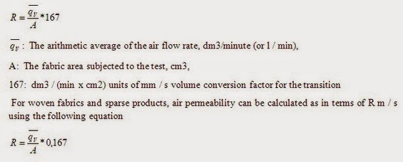
Measurement and evaluation
Read the following sentences ; then write true “T” or false “F”
Porosity is the ratio of the volume of openings (voids) to the total volume of material. Porosity represents the storage capacity of the geologic material
Factors influencing porosity in multi-layer woven fabrics
Flat textile materials, e.g. fabrics, are porous materials which allow the transmission of energy and substances and are therefore interesting materials for different applications. In general, they are used for clothing, interior and wide range of technical applications. Fabric as porous barrier between the human body an environment should support heat and water vapor exchange between the body and environment in order to keep the body temperature within the homeostasis range. Besides thermo-physiological protection, fabrics also play an important role by heat protection due to the flames or convection heat, contact heat, radiant heat as well as due to the sparks and drops of molten metal, hot gases and vapors Fabrics protect users against micro-organisms, pesticides, chemicals, hazardous particles and radiations (radioactive particles, micro-meteorites, X-rays, micro-waves, UV radiation, etc.). They act very important role also by environmental protection as filters for air and water filtrations, sound absorption and isolation materials against noise pollution, adsorption materials for hazardous gas pollution, etc. By all mentioned applications dedicated to absorption, desorption, filtration, drainage, vapors transmission, etc., the essential constructional parameter that influences fabric efficiency to protect human or environment is porosity. The fabric in a dry state is a two-phase media which consists of the fibrous material – solid component and void spaces containing air – gas (void) component. The porosity of a material is one of the physical properties of the material and describes the fraction of void space in the material. The porosity (or void volume fraction) is expressed as coefficient ranging between 0 and 1 or as percentage ranging between 0% and 100% (by multiplying the coefficient by 100). Mathematically, the porosity is defined as the ratio of the total void space volume to the total (or bulk) body volume
Materials and porosity measurements
Our experiments involved woven fabrics made from staple yarns with two restrictions: first, only fabrics made from 100% cotton yarns (made by a combing and carding procedure on a ring spinning machine) were used in this research; second, fabrics were measured in the grey state to eliminate the influence of finishing processes. We believe that it is very hard, perhaps even impossible, to include all woven fabrics types to predict individual macro-porosity parameters precisely enough, and so we focused our research on unfinished staple yarn cotton fabrics. We would like to show that genetic programming can be used to establish the many relations between woven fabric constructional parameters and particular fabric properties, and that the results are more useful for fabric engineering than ideal theoretical models. The cotton fabrics varied according to yarn fineness (14 tex, 25 tex, and 36 tex), weave type (weave value), fabric tightness (55% - 65%, 65% - 75%, 75% - 85%), and denting. The constructional parameters of woven fabric samples are collected in They were woven on a Picanol weaving machine under the same technological conditions. The weave values of plain (0.904), twill (1.188), and satin (1.379) fabrics, as well as fabric tightness, were determined according to Kienbaum’s setting theory
We used an optical method to measure porosity parameters of woven fabrics, since it is the most accurate technique for macro-pores with diameters of more than 10 m. For each fabric specimen, we observed between 50 and 100 macro-pores using a Nikon SMZ-2T computer-aided stereomicroscope with special software. We measured the following macro-porosity parameters: area of macro-pore cross-section, pore density, and equivalent macro-pore diameters.
Woven fabric’s ideal geometric model of porous structure
When a woven fabric is treated as a three dimensional formation, different types of poresare detected 1. inter-pores, e.g. the pores which are situated between warp and weft yarns (macropores, interyarn pores) and pores which are situated between fibres in themyarns (mesopores, interfiber/intrayarn pores), 2. intra-pores, e.g. the pores which are situated in the fibres (micropores, intrafiber pores). The structure and dimensions of the inter- or intrayarn pores are strongly affected by the yarn structure and the density of yarns in the woven structure. As fibrous materials, woven fabrics have, with regard to knitted fabrics or nonwovens, the most exactly determined an ideal geometrical model of a macroporous structure in the form of a tube-like system, where each macropore has a cylindrical shape with a permanent cross-section over all its length.Because the warp density is usually greater than the weft density, the elliptical shape of the pore cross-section is used to represent the situation in Figure . Macropores are opened to the external surface and have the same cross-section area. They are separated by warp or weft yarns, and are uniformly distributed over the woven fabric area. The primary constructional parameters of woven fabrics which alter the porous structure are:
Where,
(d – yarn thickness, p – yarn spacing, MP - macropore; 1, 2 indicates warp and weft yarns, respectively) To compare woven fabrics with porosity, the following porosity parameters can be calculated on the basis of the woven fabric primary constructional parameters and the ideal model of porous structure in the form of a tube-like system:
The porosity of woven fabrics can be then written in the form of Equation:
Conclusion
This study was carried out to develop a theoretical model to predict air permeability values for fabrics. The theoretical model predicts the value of the air permeability using the pore size and some fabric properties before manufacturing. D’Arcy’s formulation was used to establish an equation expressing the relationship between the air permeability of knitted fabrics and fabric structure parameters. According to the experimental results the fabric with the lowest course count per cm and yarn number in tex has the highest air permeability values. Moreover increasing the loop length produced a looser surface in the fabric and increased air permeability. As the yarn gets thinner and the pores between loops get larger the air permeability will increase accordingly. According to some formulations when the stitch density stitch length or yarn diameter increase pore size values decreases. Due to the differences between ideal and real geometry and the random variation of the fabric structure there are no exact dependence between experimental air permeability and predicted air permeability values. However the closeness of the results of predictions based on calculated values from the theoretical model and experimental values show that our model can be successfully used for the prediction of the air permeability of knitted fabrics. This model is simple and efficient. Permeability and porosity are strongly related to each other. If a fabric has very high porosity it can be assumed that it is permeable. It was also found that there is a near positive linear relationship between pore size and air permeability values hence it could be assumed that the model developed is applicable for predicting the air permeability of plain knitted fabrics produced with different fiber types.
The suggested conditions for the experiment:
- Experimental surface area = 20 cm2
- Pressure drop = 100 Pa for clothing fabrics
- Pressure drop = 200 Pa for industrial fabrics
Working Procedure
- Preparing appropriate samples in accordance with standard for the air permeability
- Conditioning the samples
- Setting the pressure and time of the air permeability test device in accordance with the sample.
- Placing the sample to the device
- Running the device
- Reading the value of air permeability of the sample from the indicator of the device at the end of the test.
- After taking the arithmetic mean of the test results, to calculate the value of air permeability.
- Repeating the test for the appropriate number of samples in accordance with standard.
One side- coated test parts should be stretch toward the edges which have lower pressure to prevent air leakage. For applying air flow towards the test part, air extractor or other vehicles are switched on and as suggested above, an air flow is adjusted until a pressure drop is created in the part of the fabric subjected to experiment. After reaching a minimum of one minute or stabilize the air flow is recorded. Under the same experimental conditions, , the experiment is repeated at least 10 times in different parts of the sample. Finally, taking the arithmetic mean of the test results, the value of air permeability is calculated.
The experiment Result
Air permeability (R) is calculated as mm / s by using the following equation.

Measurement and evaluation
Read the following sentences ; then write true “T” or false “F”
- When taken into consideration thermal properties of clothing and the interaction with body, air permeability is not affected. (… …)
- The standard used for this experiment is TS 391 EN ISO 9237 (……)
- It is necessary to ensure that there are no wrinkle regions and a visible mistake in a laboratory sample.
- Mass, from each piece that makes up the sample, a laboratory sample, the single most and at least 2 m in length is cut (……)
- Air permeability (R) is demonstrated as mm/s (……)
Porosity is the ratio of the volume of openings (voids) to the total volume of material. Porosity represents the storage capacity of the geologic material
 |
| Fig.: Pore Size vs. Porosity |
- Type of material
- Linear density of yarns “warp-weft”
- Warp and weft density per cm
- Twist factors
- Type of spinning
- Difference of denting system
- Type of stitches
- Form and relative porosity
- Type of woven construction
- Thickness & weight
Flat textile materials, e.g. fabrics, are porous materials which allow the transmission of energy and substances and are therefore interesting materials for different applications. In general, they are used for clothing, interior and wide range of technical applications. Fabric as porous barrier between the human body an environment should support heat and water vapor exchange between the body and environment in order to keep the body temperature within the homeostasis range. Besides thermo-physiological protection, fabrics also play an important role by heat protection due to the flames or convection heat, contact heat, radiant heat as well as due to the sparks and drops of molten metal, hot gases and vapors Fabrics protect users against micro-organisms, pesticides, chemicals, hazardous particles and radiations (radioactive particles, micro-meteorites, X-rays, micro-waves, UV radiation, etc.). They act very important role also by environmental protection as filters for air and water filtrations, sound absorption and isolation materials against noise pollution, adsorption materials for hazardous gas pollution, etc. By all mentioned applications dedicated to absorption, desorption, filtration, drainage, vapors transmission, etc., the essential constructional parameter that influences fabric efficiency to protect human or environment is porosity. The fabric in a dry state is a two-phase media which consists of the fibrous material – solid component and void spaces containing air – gas (void) component. The porosity of a material is one of the physical properties of the material and describes the fraction of void space in the material. The porosity (or void volume fraction) is expressed as coefficient ranging between 0 and 1 or as percentage ranging between 0% and 100% (by multiplying the coefficient by 100). Mathematically, the porosity is defined as the ratio of the total void space volume to the total (or bulk) body volume
Materials and porosity measurements
Our experiments involved woven fabrics made from staple yarns with two restrictions: first, only fabrics made from 100% cotton yarns (made by a combing and carding procedure on a ring spinning machine) were used in this research; second, fabrics were measured in the grey state to eliminate the influence of finishing processes. We believe that it is very hard, perhaps even impossible, to include all woven fabrics types to predict individual macro-porosity parameters precisely enough, and so we focused our research on unfinished staple yarn cotton fabrics. We would like to show that genetic programming can be used to establish the many relations between woven fabric constructional parameters and particular fabric properties, and that the results are more useful for fabric engineering than ideal theoretical models. The cotton fabrics varied according to yarn fineness (14 tex, 25 tex, and 36 tex), weave type (weave value), fabric tightness (55% - 65%, 65% - 75%, 75% - 85%), and denting. The constructional parameters of woven fabric samples are collected in They were woven on a Picanol weaving machine under the same technological conditions. The weave values of plain (0.904), twill (1.188), and satin (1.379) fabrics, as well as fabric tightness, were determined according to Kienbaum’s setting theory
We used an optical method to measure porosity parameters of woven fabrics, since it is the most accurate technique for macro-pores with diameters of more than 10 m. For each fabric specimen, we observed between 50 and 100 macro-pores using a Nikon SMZ-2T computer-aided stereomicroscope with special software. We measured the following macro-porosity parameters: area of macro-pore cross-section, pore density, and equivalent macro-pore diameters.
Woven fabric’s ideal geometric model of porous structure
When a woven fabric is treated as a three dimensional formation, different types of poresare detected 1. inter-pores, e.g. the pores which are situated between warp and weft yarns (macropores, interyarn pores) and pores which are situated between fibres in themyarns (mesopores, interfiber/intrayarn pores), 2. intra-pores, e.g. the pores which are situated in the fibres (micropores, intrafiber pores). The structure and dimensions of the inter- or intrayarn pores are strongly affected by the yarn structure and the density of yarns in the woven structure. As fibrous materials, woven fabrics have, with regard to knitted fabrics or nonwovens, the most exactly determined an ideal geometrical model of a macroporous structure in the form of a tube-like system, where each macropore has a cylindrical shape with a permanent cross-section over all its length.Because the warp density is usually greater than the weft density, the elliptical shape of the pore cross-section is used to represent the situation in Figure . Macropores are opened to the external surface and have the same cross-section area. They are separated by warp or weft yarns, and are uniformly distributed over the woven fabric area. The primary constructional parameters of woven fabrics which alter the porous structure are:
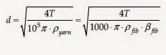
- Yarn fineness, e.g. the mass of 1000 meter of yarn from which the yarn diameter can be calculated,
- Type of weave, e.g. the manner how the yarns are interlaced. It has an effect on the pore size as well as on the shape of pore cross-section
- The number of yarns in length unit (warp and weft densities), which directly alters the pore size. When fibre properties (fibre density, dimension, and shape) are different, two woven fabrics with similar woven structures and geometrical configurations can have distinctly different porosity
 |
| Figure:. 2D and 3D presentations of an ideal model of the porous structure of a woven fabric |
(d – yarn thickness, p – yarn spacing, MP - macropore; 1, 2 indicates warp and weft yarns, respectively) To compare woven fabrics with porosity, the following porosity parameters can be calculated on the basis of the woven fabric primary constructional parameters and the ideal model of porous structure in the form of a tube-like system:
The porosity of woven fabrics can be then written in the form of Equation:

Conclusion
This study was carried out to develop a theoretical model to predict air permeability values for fabrics. The theoretical model predicts the value of the air permeability using the pore size and some fabric properties before manufacturing. D’Arcy’s formulation was used to establish an equation expressing the relationship between the air permeability of knitted fabrics and fabric structure parameters. According to the experimental results the fabric with the lowest course count per cm and yarn number in tex has the highest air permeability values. Moreover increasing the loop length produced a looser surface in the fabric and increased air permeability. As the yarn gets thinner and the pores between loops get larger the air permeability will increase accordingly. According to some formulations when the stitch density stitch length or yarn diameter increase pore size values decreases. Due to the differences between ideal and real geometry and the random variation of the fabric structure there are no exact dependence between experimental air permeability and predicted air permeability values. However the closeness of the results of predictions based on calculated values from the theoretical model and experimental values show that our model can be successfully used for the prediction of the air permeability of knitted fabrics. This model is simple and efficient. Permeability and porosity are strongly related to each other. If a fabric has very high porosity it can be assumed that it is permeable. It was also found that there is a near positive linear relationship between pore size and air permeability values hence it could be assumed that the model developed is applicable for predicting the air permeability of plain knitted fabrics produced with different fiber types.


No Responses to "Study on Air Permeability and Porosity of Fabric"