Textile Spinning Process of Cotton Yarn
Harshani Wijendra
Sri Lanka Institute of Textile & Apparel Technology (SLITA)
Email: harshani_bipasha@yahoo.com
Harshani Wijendra
Sri Lanka Institute of Textile & Apparel Technology (SLITA)
Email: harshani_bipasha@yahoo.com
What is Spinning?
A Yarn is usually of substantial length & of small cross section. In the cross section of a yarn there are usually a multiple number of Staple fibers (short fibers) or Filaments (long fibers) of unlimited length.
Yarn made out of Staple fiber is known as Spun Yarn, because the staple fibers should undergo number of process stages so that a yarn can be made out of them. This procedure or process stages in correct sequence is called “Spinning”. Fiber extrusion or conversion of filaments from Polymers was also considered as “Spinning”. Below mentioned is an introduction to the Yarns.
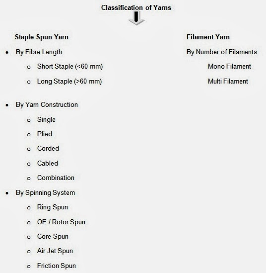 |
| Classification of Yarn |
Those are made by Twisting Staple Fibres together into a Strand. The length of the Fibre is limited. Given are some of the spun yarns.
01. Mono Yarn:
Solid, Single Strand of Unlimited Length.
02. Multi Filament :
Many continuous filaments with some twist.
03. Staple Yarn :
Many short fibers twisted together tightly.
04. Two Plied Yarn :
Two single yarn twisted together.
05. Multi Plied Yarn :
Plied Yarns twisted together.
06. Thread :
Hard, Fine, Plied Yarn.
07. Cord or Cable :
Many plied yarns twisted into a course structure.
Yarn Numbering Systems:
In above we found that there are different types of yarns. The thickness is a very important property of a yarn. So there are methods to determine & define yarn thickness. Depending on the units used for measuring Length & mass, fineness of a textile yarn is given in different units. Such systems having different units employed to indicate fineness are called Yarn Numbering Systems. There are two types of systems & they are;
- Direct System ( Mass per unit length)
- Indirect System (Length per unit Mass)
a. Tex System
This system represents the weight in grams per 1000 m length (1000m weight in grams)
b. Denier System
This system represents the weight in grams per 9000m (9000m weight in grams)
02. Indirect System
a. Count System (Ne)
In this system, count refers to the number of hank (01 hank equals to 840 yards) in one pound. This system called as English system as well.
b. Metric System (Nm)
Here it is The number of unit length of 1000 m is 1 kilogram.
Table of Yarn Numbering
| Yarn Type | Numbering System | Standard Length | Standard Weight | Count |
| Cotton | English | Hank (840 yds.) | 01 pound | Hanks / lb |
| Cotton | Metric | Kilometer | 01 Kilogram | Km / kg |
| Woolen | English | Skein (256 yds) | 01 Pound | Skeins / lb |
| Linen | Wet Spun | Hank (300 yds) | 01 Pound | Hanks / lb |
| Spun Rayon | English | Hank (840 yds) | 01 Pound | Hanks / lb |
Cotton Yarn Manufacturing Process:
In here we have discussed the process of cotton yarn manufacturing. The Initial stage of the Spinning Process involves converting Cotton in Bales into the Cone Winding.
First thing in Spinning Process is converting highly compressed Cotton in Bales into the form of thoroughly loosened, opened & cleaned State.
These Steps of processing are carried out in the Blow Room of a Spinning Mill. First stage of Spinning involves converting lightly compressed Cotton bales into the form of Opened & Cleaned Fibre Flocks.
01. Blow Room
At this process the Fibres in Bale form will be loosen, opened & cleaned. This is the starting stage of Spinning Process. There are three actions happen in Blow room machine. They are ;
The spikes of the evener roller lattice, pick up matted lumps of cotton & take them to the top of the lattice. At this point, they are met by series of spikes of the evener roller. Evener roller rotates in the clockwise direction so that spikes on it oppose any further passage of cotton. Here striking of cotton by spikes of the evener roller takes place, while being held by spikes of evener Lattice. Thereby a rough combing action also takes place. The spiked Lattice takes part of the cotton with it, while evener roller knocks the remained back, into the hopper. Hopper is a box like room in which the evener lattice is mounted. By this action, the size of the matted cotton lumps is reduced & only a portion on spikes is allowed to go forward. Fiber hanging one roller & lattice spikes are pulled in opposing directions & this pulling.
2. Action of Air Currents
The fan, which is situated at A would blow air through the duct B. This would tend to create a vaccum in the trunk C. Air can enter the system only at position D. A low pressure near vaccum is created inside C. This would result in air rushing through D due to atmospheric being higher than that inside the trunck C. The shirley wheel consists of a section of ducting by the insertion of a rotating perforated disc. This disc or wheel rotates at about 70 rpm. This is used to separate cotton, On reaching the Shirley wheel, the air is able to pass through the perforations in the wheel causes the cotton is arrested & dropped into the space below. The rotation of the wheel causes the cotton to be carried downwards through a lightly spring loaded control flap E. Cotton falls freely under gravity. The fine dust passes with the air through the perforations of the wheel. This is then discharged with air to the dust settling chamber or dust filtration system.
3. Action of Beaters
This is the action that is mostly responsible for removing impurities of Cotton in the Blow Room. Cotton fibres can be subjected to the striking action of Beaters in the following ways.
Carding is one of the most important operations in the spinning process as it directly determines the final features of the yarn, above all as far as the content of neps and husks are concerned. There are many objectives of the carding process and these can be summarized as:
And in this action you can see two actions. They are;
When two close surfaces have opposite wire direction and their speed direction or relative motion is also opposite. Then the action between two surfaces is called carding action.
Functions:
2. Stripping Action
When two close surfaces have same wire direction and their speed direction or relative motion is opposite then the action between two surfaces is called stripping action.
Functions:
This is the machine on which drafting & doubling are carried out. Carded sliver is that they are not even (uniform) enough to produce to good quality yarns. Therefore, usually all the carded slivers are subjected to Doubling & Drafting on a machine called “Draw Frame”.
Doubling is the practice of feeding two or more strands to produce one Strand. To attenuate fiber laps to slivers, Drafting is carried out. Different methods are used to draft sliver or yarn. One method is called “Roller Drafting”. During drafting the number of fibers in the cross section of the sliver or lap is reduce.
Tasks of Draw frame
Equalizing is always performed by a first process, namely doubling and can optionally also be performed by a second process, namely auto leveling. The draft and the doubling have the same value and lie in the range of 6 to 8.
Parallelizing: To obtain an optional value for strength in the yarn characteristics, the fibers must be arranged parallel in the fiber strand. The draw frame has the tasks of creating this parallel arrangement. It fulfills the task by way of the draft, since every drafting step leads to straightening the fibers.
Blending: In addition to the equalizing effect, doubling also provides a degree of compensation of raw material variation by blending. Their results are exploited in particular way in the production of blended yarns comprising cotton or synthetic blends. At the draw frame metering of the individual components can be carried out very simply be selection of the number of slivers entering the machines.
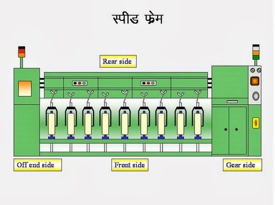
04. Roving Frame / Speed Frame
The product delivered by roving machines is called Roving. Roving is a Fibre strand of lesser count than that of a sliver. It is also has a small twist to keep Fibres together. It is wound on to a package which is suitable for feeding spinning machines.
Objectives of speed frame
To reduce the weight /unit length of sliver to make it suitable for ring spinning system.
Twisting:
To insert small amount of twist to give required strength of roving.
Winding:
To wind the twisted roving on to bobbin.
05. Combing
Combing is a process which is introduced into the spinning of finer and high quality yarns from cotton. The carded materials (sliver) contain certain amount of short fibres, neps, fine kitty and leaf particles. Short fibres are a hindrance to spinning of finer counts where the number of fibre in the cross section of the yarn is less. The short fibres cause thick and uneven places in the yarn length and the yarn looks hairy. Apart from this, very short fibres do not contribute anything to yarn strength. Short fibres below a certain pre-determined length can be easily separated out by using comber.
Objects of Comber:
One article has written about basic principle of a comber. So here only title of comber principle is given below.
06. Ring Frame
The ring spinning machine was first invented in 1828 by the American Thorp. In 1830, another American scientist, Jenk, contributed the traveler rotating on the ring. There have been many development has done in ring spinning machine for the last years but the basic concept remained unchanged.
Functions of ring frame:
Some other modern spinning systems:
In ring spinning machine twisting and winding are done simultaneously. That’s why the power consumption is higher.
07. Cone Winding
This is the final stage in Spinning & that is Cone Winding. As nowadays good winding is the mirror of spinning mills, it is necessary that this process is understood very well by all the personnel handling the department. Yarn winding can thus be viewed as simply being a packaging process, forming a link between the last few elements of yarn manufacturing and the first element of fabric manufacturing process. Improper utilisation of the features of the winding machine can not only cost heavily to the spinning mills, but it can also lead to loss of good customers permanently.
Bale Opening
↓
Blow Room
↓
Carding
Below mentioned is how the Man-made Fibers manufacturing Process.
↓
Blow Room
↓
Carding
 |
Bale Opening
↓
Conditioning of MMF Fibers
↓
Blending
↓
Blow Room
↓
Carding
↓
Drawing 1
↓
Drawing 2 (with Auto Leveler)
↓
Speed Frame
↓
Ring Frame
↓
Cone Winding
↓
Conditioning of MMF Fibers
↓
Blending
↓
Blow Room
↓
Carding
↓
Drawing 1
↓
Drawing 2 (with Auto Leveler)
↓
Speed Frame
↓
Ring Frame
↓
Cone Winding
First thing in Spinning Process is converting highly compressed Cotton in Bales into the form of thoroughly loosened, opened & cleaned State.
These Steps of processing are carried out in the Blow Room of a Spinning Mill. First stage of Spinning involves converting lightly compressed Cotton bales into the form of Opened & Cleaned Fibre Flocks.
01. Blow Room
At this process the Fibres in Bale form will be loosen, opened & cleaned. This is the starting stage of Spinning Process. There are three actions happen in Blow room machine. They are ;
- Action of Opposing Spikes
- Action of Air Current
- Action of Beaters.
 |
| Action of Opposing Spikes |
2. Action of Air Currents
 |
| Action of Air Currents |
3. Action of Beaters
This is the action that is mostly responsible for removing impurities of Cotton in the Blow Room. Cotton fibres can be subjected to the striking action of Beaters in the following ways.
- Striking the Cotton while being carried by Air Currents.
- Striking the Cotton while being held by a pair of feed rollers or paddles & pedal rollers.
Carding is one of the most important operations in the spinning process as it directly determines the final features of the yarn, above all as far as the content of neps and husks are concerned. There are many objectives of the carding process and these can be summarized as:
- Opening the tufts into individual Fibres.
- Eliminating all the impurities contained in the Fibre that were not eliminated in the previous cleaning operations.
- Selecting the Fibres on the basis of length, removing the shortest ones.
- Removal of neps.
- Parallelizing and stretching of the Fibre.
- Transformation of the lap into a sliver, therefore into a regular mass of untwisted Fibre.
 |
| Carding Machine Diagram |
- Carding Action
- Stripping Action
When two close surfaces have opposite wire direction and their speed direction or relative motion is also opposite. Then the action between two surfaces is called carding action.
Functions:
- It is occurred between flats and cylinder.
- Maximum individualization of fibers is achieved in this region.
- Naps short fibers dirt and dust are removed by this action.
- There always should be point against point action.
 |
| Carding Action |
When two close surfaces have same wire direction and their speed direction or relative motion is opposite then the action between two surfaces is called stripping action.
Functions:
- It is occurred between licker in and cylinder.
- There are should be point against back action.
- Individualization of Fibre is also by this action.
This is the machine on which drafting & doubling are carried out. Carded sliver is that they are not even (uniform) enough to produce to good quality yarns. Therefore, usually all the carded slivers are subjected to Doubling & Drafting on a machine called “Draw Frame”.
Doubling is the practice of feeding two or more strands to produce one Strand. To attenuate fiber laps to slivers, Drafting is carried out. Different methods are used to draft sliver or yarn. One method is called “Roller Drafting”. During drafting the number of fibers in the cross section of the sliver or lap is reduce.
 |
| Draw frame |
- Equalizing
- Parallelizing
- Blending
Equalizing is always performed by a first process, namely doubling and can optionally also be performed by a second process, namely auto leveling. The draft and the doubling have the same value and lie in the range of 6 to 8.
Parallelizing: To obtain an optional value for strength in the yarn characteristics, the fibers must be arranged parallel in the fiber strand. The draw frame has the tasks of creating this parallel arrangement. It fulfills the task by way of the draft, since every drafting step leads to straightening the fibers.
Blending: In addition to the equalizing effect, doubling also provides a degree of compensation of raw material variation by blending. Their results are exploited in particular way in the production of blended yarns comprising cotton or synthetic blends. At the draw frame metering of the individual components can be carried out very simply be selection of the number of slivers entering the machines.
04. Roving Frame / Speed Frame
The product delivered by roving machines is called Roving. Roving is a Fibre strand of lesser count than that of a sliver. It is also has a small twist to keep Fibres together. It is wound on to a package which is suitable for feeding spinning machines.
Objectives of speed frame
- Attenuation of draw sliver to a suitable size for spinning.
- To insert a small amount of twist to strengthen the roving.
- To wind the twisted strand roving into a bobbin.
- Drafting
- Twisting
- Winding
To reduce the weight /unit length of sliver to make it suitable for ring spinning system.
Twisting:
To insert small amount of twist to give required strength of roving.
Winding:
To wind the twisted roving on to bobbin.
 |
| Roving frame |
Combing is a process which is introduced into the spinning of finer and high quality yarns from cotton. The carded materials (sliver) contain certain amount of short fibres, neps, fine kitty and leaf particles. Short fibres are a hindrance to spinning of finer counts where the number of fibre in the cross section of the yarn is less. The short fibres cause thick and uneven places in the yarn length and the yarn looks hairy. Apart from this, very short fibres do not contribute anything to yarn strength. Short fibres below a certain pre-determined length can be easily separated out by using comber.
Objects of Comber:
- To remove the short fibres below a pre-selected length so that the spinner enable to produce finer or better quality of yarn that cannot be possible in carding state.
- Elimination of remaining impurities.
- Elimination of large proportion (not all) of the neps in the fibre.
- Formation of sliver having maximum possible evenness.
- To straighten the fibres.
One article has written about basic principle of a comber. So here only title of comber principle is given below.
- Lap feeding by feed roller
- Lap nipping by the nipper
- Combing by the cylinder
- Nipper opening and forwarding
- Detaching roller backward movement
- Piecing
- Combing by the top comb
- Detaching roller forward movement
- Starting a new cycle
- Cleaning of cylinder comb
 |
| Combing machine diagram |
The ring spinning machine was first invented in 1828 by the American Thorp. In 1830, another American scientist, Jenk, contributed the traveler rotating on the ring. There have been many development has done in ring spinning machine for the last years but the basic concept remained unchanged.
 |
| Ring spinning machine |
- Draft the roving until the required fineness is achieved
- Twist the drafted strand to form yarn of required count and strength
- Winding the twisted yarn on to the bobbin for suitable storage, transportation and further processing.
Some other modern spinning systems:
- Open end rotor spinning system
- Air Jet spinning system
- Friction spinning system
- Wrap spinning system
- Any type of material (Fibre) can be spun
- Wide range of count can be processed
- It delivers a yarn with optimum characteristics.
- Idealized twisting system
- It is uncomplicated and easy to operate
- Higher yarn strength can be achieved
- Low production
- Machine generates more heat
In ring spinning machine twisting and winding are done simultaneously. That’s why the power consumption is higher.
07. Cone Winding
This is the final stage in Spinning & that is Cone Winding. As nowadays good winding is the mirror of spinning mills, it is necessary that this process is understood very well by all the personnel handling the department. Yarn winding can thus be viewed as simply being a packaging process, forming a link between the last few elements of yarn manufacturing and the first element of fabric manufacturing process. Improper utilisation of the features of the winding machine can not only cost heavily to the spinning mills, but it can also lead to loss of good customers permanently.
 |
| Cone Winding Machine |