Halo Sobat ! | Members area : Register | Sign in
About me | SiteMap | Arsip | Terms of Use | Dcma Disclaimer

Footer

Powered by Blogger.

Social Icons

Featured Posts

Slider(Do not Edit Here!)

Minha lista de blogs

Publicidade 2

Cantinho do Blog

Parcerias

Hospedagens FREE

Dominios FREE

Publicidade 1

widget

Pojok Blog

Arsip

Sample text

Sample Text

Sample Text

Powered By Blogger
Powered By Blogger
Powered By Blogger

Perangkat SD

Perangkat SMP

Berita Pendidikan

Pengumuman

..::Aprendiz MUOnline::..

..::Ultimate Vendas::..

..::Central MU Online::..

..::Criando Portais::..

..::Viciados MU::..

..::Universe Divulgação::..

Visitor Counter

Google Search

..::Mixer Divulgação::..

You can replace this text by going to "Layout" and then "Page Elements" section. Edit " About "

..::Rádios Online::..

Recent Comments

..::Melhor Divulgação::..

..::Vermelho Divulgação::..

..::Extreme Divulgação::..

..::Control Downs::..

..::Divulgaçao::..

..::FreeXat parceiro top::..

..::Ciados MU Online::..

..::Nosso Banner no seu Site::..

About Me-

Seguidores

Seguidores

Social Icons

Musik

Translate

..::Majestic Hacker::..

..::Exclusivo MU Online::..

Translate to your language

Fox Life

Pages

Pages

Publicidade

Parceiros

Social Icons

New Developments on Draw Frame Machines

Friday, 7 February 2014

Introduction:
The Draw Frame is another important machine of the spinning mill because it also magnifies the yarn. Quality of yarn is directly related to the quality of Draw Frame Sliver, so the modern developments are carried out produce better Draw Frame sliver. There are some common developments which are evolved such as Auto leveler, Can Changing systems, suction devices etc… These are developing day by day to be more precise by means of electronic and mechanical improvements. 
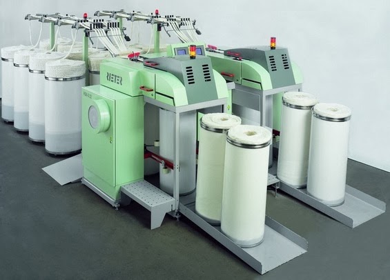
Modern Draw Frame


Followings are some of other new developments.
  • Auto break draft setting - Incorrect break draft increases yarn U%. When there are imperfections and neps, the total draft does not affect yarn quality much. So break draft plays a very significant role in yarn quality and must be set correctly. In Trutzschler new draw frames has this Technology and it optimize the sliver by estimating the corresponding values of the break draft merely in one minute and takes important parameters, like fibre-fibre friction, fibre to metal friction, etc and calculate the break draft.
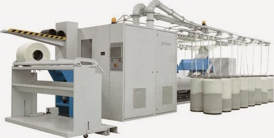
    Draw Frame and lap machine combined
  • CLEANcoil - The deposition of spin finish on the underside of the coller plate of draw frame when processing MMF leads to displacement of the sliver layer in can. To avoid this, the coller has to be cleaned frequently resulting in production loss. Rieter has patented a coller plate that has honeycomb like surface and claimed to reduce cleaning frequency from 2 to 3 hours to 1 - 3 days depending upon the type and quantity of finishing agents. 

  • Pneumatic Pressure Head for the drafting rollers. This technology can control the pressure for sliver automatically and from that better fibre control can be achieved. 

  • Tension measuring system – when the card sliver is fed to the draw frame, there is a long path to travel. So on way there will be tension variations due to friction forces and weight of the sliver. To avoid these tension variations there are tension measuring sensors to detect and adjust the roller speeds according to it. 

  • Short-term auto levelers - In principle, leveling takes place in the entire speed range of the draw frame. Even when reducing speed before and during run-up after a can change, short-term leveling (SERVO DRAFT) remains in operation. Due to this each meter of draw frame sliver has its optimum quality. 

  • Use a camera to monitor the sliver quality – This is used to monitor the output sliver behalf on quality aspects such as fibre arrangement, fibre imperfections and irregularities. This is done by using a camera which capture images of the output sliver and compared with the references by means of image processing techniques. When there is an imperfection, the machine is automatically adjusted to eliminate by varying the machine speed etc…


  • Simple and automatic adjustment of drafting zone widths - The drafting system rolls are precisely positioned on parallel guides. Since the nip distance can be set by reading on a dial, it is not necessary to use any gauges. Top roll support, top rolls and bottom cylinders are firmly connected to each other and are automatically adjusted as well. Due to a special belt guide, it is not necessary to tension again the belts after readjustment. 

  • Use of microwave sensors – this is used in auto leveling to determine band mass of an elongated, substantially non twisting fibre structure. This is used the moisture content of the sliver as the measuring principle. 

  • Thread monitor and a slubbing clamping device – In this amount of light transparency through the sliver is monitored. To do this principle, there are photo cells to capture the light form the light source. There will be a shadow (light intensity variation) which is generated according to sliver and it is monitored and processed through high level of technology. When there is a thick place the transparency of light will be lower and it is identified form the photo cell. When a sliver slub is monitored, the back rollers are clamped for a instant time and eliminate the slub.
References:
  1. Trutzschler - http://www.cardclothing.de (Accessed on 18 October 2009)
  2. Rieter Draw Frame - http://www.rieter.com/en/textile/short-staple-yarn/fiber-preparation/c-60-card/ (Accessed on 18 October 2009)
  3. http://www.indiantextilejournal.com/articles/FAdetails.asp?id=2010 (Accessed on 18 October 2009)
  4. http://www.marzoli.it/marzoli/documents/stiratoio_monotesta.pdf (Accessed on 18 October 2009)
  5. http://www.patentstorm.us/patents/pdfs/patent_id/7103440.html (Accessed on 19 October 2009)
  6. http://www.freepatentsonline.com/4450677.pdf (Accessed on 19 October 2009)

Recent Development of Carding Machine

Thursday, 30 January 2014

Background of Carding Machine:
In 1748 Lewis Paul of Birmingham, England invented the hand driven carding machine . The name card is derived from the latin “Carduus. It mans thistle, the spiked fruit of which was used for plucking fibred apart in earlier time.

The proverbs of experts,
  • “The card is the heart of the spinning mill”
  • ‘Well-carded is half-demonstrate the immense significance of carding for the final result of the spinning operation.
These proverbs demonstrate the immense significance of carding for the final result of the spinning operation. The importance of carding is still greater where new spinning systems are concerned. The considerable influence of the card on yarn quality arises from the very complex series of events in the process itself, and also from the pressure to adopt an extremely high production rate on economic ground.

Carding is defined s the reduction of entangled mass of fibers to filmy web by working them between two closely spaced relatively moving surfaces clothed with sharp points. It is a preliminary process in spun yarn technology just after blow room process.

Recent Developments of Carding Machine:

In previous discussed that on 1748 Lewis Paul of Birmingham, England invented the hand driven carding machine. This carding machine has been added many values and developed for the requirement of spinners.
Modern Carding Machine
The most recent developments are given below:
  • Higher production rate up to 250 kg/hour
  • Direct feeding system FBK: Chute feed
  • Feed rate control system: CFD(CORRECTA FEED)
  • Multiple licker-in system: 3 Licker-in
  • Precision Flat Setting System PFS
  • Precision Mote Knife Setting System PMS
  • Aluminum flats without bolted connection
  • Computer control with Touch Screen
  • Electronic Flat Measuring System FLATCONTROL TC-NCT
  • ON-line nep counting with NEPCONTROL TCC-NCT
  • Waste quality measuring with WASTECONTROL TC-WCT
  • Digitally controlled, maintenance-free servodrives
  • Integrated Carding Grinding system:
  • IGS Tops
  • IGS Clssic
  • Magnetic flat bar: MAGNA TOP
  • Integrated and continuous suction system
  • Larger can size: 1000X1200 mm
  • Roller doffing system
GRINDING & ITS IMPORTANCE:
There are three areas in any carding machine. These are:
  1. Opening & Cleaning area
  2. Carding area
  3. Sliver formation
The main segments of carding machine are covered by card clothing. These metal cloth with sharp wire. The wire looses its sharpness due to metal to metal or metal to fibre friction. That’s why it needs re-sharpening. The process re- sharpening he car clothing wire is called

GRINDING
The performance of card clothing reduces continuously with the processing of materials. The operating life of clothing expressed in terms of the total throughput or material. For the cylinder it normally lies between 300 tons to 600 tons. But it can be higher for some circumstances. The amount of fibre, type of fibre etc. could be the reason. Processing of fibers strongly wears down the teeth-they become rounded of the sliver. The points must therefore be sharpened from time to time, in order to give a better shape to the edges by grinding them. Each grinding operation reduces the number of neps, but the level nerve returns to that prior to the preceding grind.The deterioration in quality from one grinding interval to the nest arises from the fact that the teeth are ground down to successively lower heights, the land at the teet points become stadily larger, and softer metal layers are gradually exposed. The interval is best selected in dependence upon the nep limit. The doffer clothing works much less than that of the cylinder works. That’s why it should be ground less frequently except when synthetic fibres are being processed.The clothing on the Taker- in should not be ground. It should be renewed after a throughput of 100 tons to 200 tons. The grinding tools: There are types of grinding tools are commonly in use.

These are:

  • The full-width grinding roller
  • The traversing grinding disc
Developments in Licker-in Section of Carding Machine:
Automation, higher production and improved quality of the products are the requisite of any recent developments.

Chute feeding is a recent development in feeding small tufts of cotton fibres directly from blow room to a series of cards, arranged in a circuit through ducts and chutes. Already we have seen the working of chute feeding system in a third unit.. In this unit, we shall discuss some other developments in licker-in section of carding one by one in the following pages.

The objects of major developments in licker in section that have taken place are
  • To improve the opening of tuft at high rate of feed in H. P card.
  • To distribute the tufts as evenly as possible on the cylinder.
  • To extract the maximum trash with minimum loss of spinnable fibres.
Following are the developments that have taken place in the licker-in section.
  1. Card analyser
  2. Development in place of mote knife
  3. Shirley modification.
  4. Fibre retriever.
Card Analyzer or Uni Opener:
M/S. Nagoya a leading card clothing manufacturer of Japan has offered an evener roller under the trade name of card Analyser. This may also be called as uniopener. As shown in fig, this evener roller is placed above the licker in. It opens the large unopened tufts released by the licker-in and also remove the excess fibres on the cylinder which is returned to the feed roller again through a space provided between the taker-in and its cover. Thus it helps to feed the tufts as evenly as possible on the cylinder. It is claimed that the neps formation and the waste are reduced.
Fig: Card analyzer or uni opener
Development in Place of Mote Knife:
M/S. Mafatlal Engineering has introduced comb bar and wast control knife attachment in their super card in place of mot knives, as shown in fig.
Development in Place of Mote Knife
The arrangement consists of a small diameter cylinder clothed with coarse pitch wire. It replaces conventional mote knives when processing cotton and is positioned directly under the feed plate nose so that the material feed is immediately subjected to carding action. This opens the cotton and gives high trash yield by permitting the trash to separate from the main stream of fibre in the large free space following the comb bar.

Shirley Modification :
The essential changes in the cleaning region are: 1. The replacement of conventional mote knives by a deflector plate which is provided under side of the feed plate.
Shirley Modification
The taker-in grid is replaced by a shorter grid usually 7” long, incorporating 3 bars and the normal perforations. & The Setting between grid and taker-in is made wider than the conventional card. A safety guard is fitted under the feed plate to cover the exposed portion of the taker-in. For short staple cotton 8” grid is usually suitable, for medium 7” grid and for long staple cotton 6” grid may be employed.

Advantages of Shirley Modification:
  1. The amount of trash passed on to the cylinder was 31% less than normal resulted in cleaner sliver.
  2. The dust generated during carding -is reduced.
  3. The life of the metallic clothing is increased due to less trash on cylinder.
  4. Increases the trash extraction of 10% with 24% less lint loss than conventional card.
Fiber Retriever :
This arrangement reduce the loss of spendable fibers.
Fiber Retriever
The nose of the fibre retriever deflects the heavier trash particles, downwards away from the licker-in. Air drawn in by the fast rotating licker-in is channelled between the buffle plates of fibre retriever, so that the trash particles fall downwards in the up current of air, which detaches any spinnable fibre entangled with the trash particles and carries the good fibres back to the licker-in. It is claimed that as much as 1 % waste is reduced.

Dust Extraction Systems in Carding

The high pressure area in the card-at the junction between cylinder and flats at taken-in end-causes ejection of dust over top of the back plate and between the flats. Another high pressure area- at the junction between the main cylinder and doffer -leads to ejection of dusty air over the doffer Doffer comb produces air turbulences, which causes dust to rise and at the calender roller the air that is mixed with the cotton in the web is squeezed out, together with dust and fly. Air escaping into the atmosphere from the high pressure zone carries dust with it and is responsible for most of the dust in the card room. Modern HP cards are equipped with the dust and fly collector such as shirley pressure point system for extracting the dust, fly and fibres which are collected in a special chamber without rendering unhygienic the atmosphere in the card room.

This has low running cost and useful
  1. To prevent the ejection of dust by suitably covering the regions of the machine where the dust is liberated.
  2. To move the dust from several forces to a central region from which it can be conveniently removed.
An Exhaust fan, through suitable hoods fitted to critical regions of the card draw off air with fly and dust and after separating these from air, pure air is returned to the department. The dust passing through the slits between the flats is retained (and then exhausted) by a flexible metal sheet across the full width of flats and placed inside the flat chain to cover about 2/3 of the flats.
Shirley pressure point exhaust system
The region where flats take position on the bend is also boxed in and exhausted. A deflector shield is fitted over the doffer comb and extends forward to the calender roller and the region under the calender roll is boxed in to collect the fly that falls from the under side of web. A screen of perforated metal is fixed in front of the flat cleaning brush to catch any fly released there, and a similar screen is fitted on the coiler where the sliver turns through a right angle to proceed to the can. The complete shirley pressure point system reduces the dust load in the card room atmosphere by about 90%.

Following are the improved waste removal system of latest high production carding,

Internal Suction System:
The integral fan for internal suction creates a vacuum with in the outer shell. Thus no dust from the card escapes into. the workroom. the suction is very effective in the removal or fly waste, dust and micro dust which are released during carding. Dust and wastes are removed at all points of occurence, feed, flat entry, flar strips, web delivery and waste chamber under the card. The internal suction operates continuously there by maintaining constant autodymanic conditions in the card.

The exhaust air is conveyed to air conditioning system. The amount of exhaust air is 2300 m3/h per card. Under card waste removal system.: . The under card waste are transferred by programmed periodic blasts of compressed air into the vicinity of a suction hood and collected in the rear most filter of the two filters built into the outer shell. The over card wastes including flat strips are collected in the foremost filter. The intermittently acting central suction system programmed to empty first the foremost filter and then the rear most filter. The card can be connected to a continuously acting suction system in which case there is no need for fan and filters. manual cleaning of filter is necessary in the absence of central suction system.

Different Working Parts of Carding Machine: 
Fiber Preparation:
Fig: Fiber preparation
Card Preparation:
Card Preparation
Draw Frame :
Draw Frame
Sliver Focus:
Sliver Focus
Modern Carding Machine :
Modern Carding Machine
Conclusion:
Carding is the process of arranging the fiber in parallel fusion. This is necessary for all staple fiber. Otherwise it would be impossible to produce fine yarn. Before the raw stock can be made into yarn, the remaining impurities must be removed. The fiber must be in different angle & they must be straight turned. The card is the hard of the spinning mill & well carded is half spun. Demonstrated the immersed significance of carding for the final of opening operation.

Cotton Yarn Spinning Process

Monday, 26 August 2013

Cotton Yarn Manufacturing Process

Ramandeep Singh
B.Tech, Dept. of Textile Engineering
Giani Zail Singh Punjab Technical University Campus,
Bathinda, Punjab, India
Email: rmnsandhu3335@gmail.com


Spinning:
Spinning is the first steps of textile product processing. The process of making yarns from the textile fiber is called spinning. Spinning is the twisting together of drawn out strands of fibers to form yarn, though it is colloquially used to describe the process of drawing out, inserting the twist, and winding onto bobbins. There are different types of spinning, the most commonly forms of spinning are: Ring, Rotor spinning, Air Jet, Friction etc. Now I will discuss about cotton spinning process.

Flowchart in Blowroom:

UNIFLOC(A-10)
UNIFLOC(A-10)
OBJECTS:
  1. The basic objective of unifloc ix to open the bales into smaller and lighter tuffs or floc.
  2. To transfer this materials to the various other machine of blowroom line for further processing.
The Unifloc is the first step in material processing spinning Mill. It successively opens the raw material into minituffs.

The Unifloc severs the purpose in an unrivalled way the secret lies in the well thought out construction of the take-off unit. The toothed disc of the opening roller are arranged so as to cause a tumbling action therefore by preventing the formation of furrows on the bales..

The setting of unifloc system depend upon two factor:
  1. Overall production of the unit
  2. Length of the belt
Technical Data:
  • Make „„„„„„„„„„„„„„„„„„„Trutzschler
  • Model „„„„„„„„„„„„„„„„„„„Unifloc A10 
  • Machine weight „„„„„„„„„„„„2700kg
  • Max.work of depth „„„„„„„„„1.7m
  • Production up to „„„„„„„„„„„,1000kg/h
UNICLEAN (B1)
INTRODUCATION:
The uniclean is the efficient cleaning and machine in the first stage after the unifloc . Material coming from unifloc and waste opener is sent to uniclean.

In Uniclean a cylinder equipped with pin which lead the material several times (six times) over a separating surface consisting of triangular grid bar. This process is entirely mechanical.

The cleaning principle separates the tufts exposing dust which is eliminated together with fibers fragment and small trash particles through a special continuous suction system by means of a control panel .The relative waste amount and the cleaning intensity can be entered directly. The cylinder are automatically adjusted according to these values. In combination with the unifloc a separates working point for each assortment can be defined when several types of raw material are being processed.

Technical data:
  • Make „„„„„„„„„„„„„„„„„„„„„„,Reiter
  • Model „„„„„„„„„„„„„„„„„„„„„„UnicleanB1
  • Year „„„„„„„„„„„„„„„„„„„„„„„ 1992
  • M/c weight „„„„„„„„„„„„„„„„„„,1220kg
  • Waste % „„„„„„„„„„„„„„„„„„„„,1-1.5kg
  • Pin roller weight „„„„„„„„„„„„„„„,165kg
  • Pin roller rotate „„„„„„„„„„„„„„„„480-800rpm
  • Production up to „„„„„„„„„„„„„„„1000kg
CVT3
This main purpose of CVT3 is to open the material thoroughly and to remove trash if any form cotton. A diagram of CVT3 is shown in the figure.

Working Principle:
These work on the principle of passing cotton over different cylinder having relative velocity to each other. cotton is fed in machine through the conveyer belt. Pressure roller provides the limited supply of cotton while the feed roller provides limited as well as proper supply of cotton. In cvt3 are three cylinders first having needle clothing while second and third having metallic clothing. Speed of middle beater is more than first beater while speed of third beater is more than second beater. First beater having needle clothing convert big flocks of cotton in smaller flocks while 2nd and 3rd converts them into individual fibre

Technical data:
  • Make „„„„„„„„„„„„„„„„Trutzschler
  • Model „„„„„„„„„„„„„„„,CVT 3 
  • Year „„„„„„„„„„„„„„„„„2003 
  • M/c width „„„„„„„„„„„„„1220mm
  • M/c length „„„„„„„„„„„„„2455mm
  • 1st beater speed „„„„„„„„,960-1760rpm
  • 2nd beater speed „„„„„„„„1840-2804rpm
  • 3rd beater speed „„„„„„„„,1790-3570rpm
  • Beater dia „„„„„„„„„„„„„,250mm
  • Air intake rate „„„„„„„„„„,3000+10%m3/h
Dustex
Cotton delivered by the cvt3 is enough open to feed this into the card. But this opened cotton contains some dust particles which create problem to the labour working in spinning mill. So dust should be removed from the cotton before feeding the cotton to card.

Working Principle:
Fast moving Cotton having dust particles is allowed to hit the perforated wall where cotton being bigger in size is stopped there while small dust particles because of inertia travel by the small holes of the perforated wall. So dust gets separated from the cotton.

Technical data:
  • Make „„„„„„„„„„„„„„„,Trutzschler
  • Model „„„„„„„„„„„„„„„Dustex 38 
  • M/c width „„„„„„„„„„„„1864mm
  • Total length „„„„„„„„„„„2150mm
  • Total height „„„„„„„„„„„2650mm
  • Material suction „„„„„„„„200-250pa
  • Dust extraction „„„„„„„„,300-400pa
  • Material feed „„„„„„„„„„150-200pa
Card:
Carding is the heart of the spinning industry. Carding is carried out by passing entangled fibres between closely spaced surfaces of cylinder and flats covered with sharp metal teeth .The surfaces are moved relative to each other and so the fibres are disentangled .

OBJECTIVES OF CARDING:
  1. The carding machine opens the folks of fibres to individual fibre stage.
  2. Removal of impurities.
  3. To remove the neps and short fibres from cotton. 
Material flow:
Setting of card
Sr.no.                               
Set point
Gauge(thou)
1.
Feed plate to1st l-in
30
2.
Mote knife to l-in
40
3.
Combing segment to 1st l-in
30
4.
Mote knife to 3rd l- in
60
5.
3rd l-in to cylinder
7
6.
Back bottom plate
34
7.
Back sweb clearer
16/14
8.
Back mote knife
20
9.
Cylin-to flat guage
8,8,7,7,
10.
Front top plate
3/6
11.
Front top sution hood
13
12.
Cylinder to doffer
4/5
 
Paramiters
  • Feed roll dia 100mm
  • 1st l-in dia 172.5mm
  • 2nd l-in dia 172.5 mm
  • 3rd l-in dia 172.5mm
  • Cylinder dia 1287mm
  • Doffer dia 700mm
  • CYLINDER SPEED=(494-604)rpm
  • LICKER-IN SPEED:
  • 1ST=945-1230
  • 2ND=1467-1909
  • 3RD=1922-2502
  • Doffer speed (120-180)rpm
  • DRAFT=60-250fold (120fold)
  • FLAT SPEED=320mm/min
  • Dfk pressure 0-999pa (300pa)
  • Fineness .066-.197Ne (.135Ne)
  • Ppsi cylinder rolls 860
  • Ppsi doffer 360
  • PRODUCTION = 41-52.5kg/h
Change positions
  • Motor pulley
  • Cylinder pulley
  • Licker-in pulley
  • Change wheel for draft between doffer and stripping roll
  • Change wheel for draft between stripping roller and squeezing roller
  • Change wheel for draft between calendar roller and coiler roller
  • Flat speed change gear
Can dimension
  • Can diameter - 24 inch
  • Height (from ground) - 48 inch
Maintenance points in cards
  • Check for flat loading
  • Abnormal sound in m/c
  • Machine heating up
  • Smooth web material
  • Chute filling
  • Waste suction
  • Safety doors and covers
  • No air leakages
Special feature of card
  1. centrally chute feed system for entire card
  2. automatic can changer
  3. total coverd body
Cleaning schedule
  • Genral cleaning 3days
  • Full cleaning 1month
Labour employed
  • Oprater 1
  • Reliver 1
  • Floor cleaner 1
Pre-comber Drawframe
Although the fibres are separated up to individual state but they are in random disorganized manner in the card sliver. Draw frame straightens and align the fibre along the axis of the sliver in order to have strong and even spinning
Technical data:
  • Manufacturer: Rieter.
  • Model: SB2
  • Year: 1994
  • No. of machines: 2
Machine description:
  • Input material: card sliver
  • Total no of cans: 6x2=12
  • No. of doublings: 6
  • No of coiling head: 2
  • Output: sliver
  • Drafting system 3/3
  • Total draft range 4.24-12.15
  • Delivery speed 650- 800m/min
  • Length of delivery 10750m/min
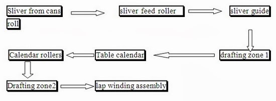
Lap Preparation
Sliver from card which is passed through the breaker drawframe is not suitable to feed in the comber because the feed material or the comber is lap sheet so preparation process known as lap preparation is done and machine used for the preparation is known as lap winding machine.

Objective of lap preparation:
  1. To make even feed for comber
  2. To present sliver hooks as leading hooks to the comber
  3. To make the fibre more parallel
Material flow chart
Machine data:
  • Manufacturer: Rieter
  • Model: E32 
  • No of machines: 2
  • No of doubling 26
  • No of delivery 1
  • Drafting system 3/3 
  • Draft: 1.36-2.2 
  • Drafting system: 2 zone drafting system
  • Delivery speed 124m/min
  • Sliver count range: 3.3-6kTex
  • Doubling: up to 28 folds
  • Length of delivery 240m
Comber
Combing is the process which is used to upgrade the raw material. It influences the following yarn quality
  • yarn evenness
  • strength
  • cleanness
  • smoothness
  • visual appearance
In addition to the above, combed cotton needs less twist than a carded yarn.

TASK OF THE COMBER:
  • To produce an improvement in yarn quality, the comber must perform the following operation.
  • elimination of short fibres as noil
  • elimination of remaining impurities
  • elimination of neps
  • The basic operation of the comber is to improve the mean length or staple length by removing the short fibres.
  • Trailing hooks from carding should be fed as leading hooks to reduce long fibre loss in the noil
SEQUENCE OF OPERATION IN A COMBER
  • Feeding, lap is fed by feed roller
  • fed lap gripped by the nipper
  • gripped lap is combed by circular comb
  • detaching roller grips the combed lap and moves forward
  • while the detaching roller delivers the material, top comb comes into action to further clean the lap
  • While going back, nipper opens and receives a new bit of lap.
Types of feeds:
  1. Forward feed (concurrent feed):Feed of the sheet into the nippers occurs while the nippers move towards the detaching roller
  2. Backward feed (counter-feed): Feed of the sheet occurs during return of the nippers.
PRODUCTION CALCULATIONS
Production of the comber is dependent upon the following:

  • N- Nips per min
  • S- feed in mm/nip
  • G- lap weight in g/m
  • K- Noil percentage
  • A- tension draft between lap and feed roller(from 1.05 to 1.1)
  • E- efficiency
THERE ARE 8 COMBERS IN HALL 1&2 
  • No of heads=8
  • Noil %=16.5%
  • Nips/min=450-458
  • Feed/nip=4.7-5.2mm
  • Length of delivery=6290
  • Delivery rate=215m/min
  • Drafting system=3/3
  • Noil suction pressure=12-15mm of water column
  • Time taken to fill up a can=29min
  • Sliver weight=4.720ktex
Technical data:
  • Manufacturer: Rieter
  • Model: E65
  • Year: 2006
  • Nos. 8
Input feed:
  • Lap width: 270-300mm
  • No. of lap per machine: 8
  • Batt weight per meter: 60-80 gm/mt
Production data:
  • Lap diameter: up to 650mm
  • Feed per nip: 4.3/4.7/5.2/5.9mm
  • Noil: 8-25 %
  • Drafting system: 3/5
  • Doubling: 8 fold
  • Sliver weight: 3-6 kTex
  • Break draft: 1.14-1.5
  • Total draft: 9.0-23.1
Pressure:
  • Loading: pneumatic
  • Top detaching roller: 3-4bar
  • Drafting system front roll: 2.5-3bar
  • Drafting system 2nd and 3rd rolls: 3.5-4.5bar
Drawframe
Sliver from comber before feeding to speed frame is passed through drawframe to get maximum possible evenness which result in the even roving at roving frame.

Objectives:
  1. To make sliver with maximum possible evenness.
  2. To make required hank for input in speed frame.
Material Flow Chart :
Material flow on the Drawframe is given by following flowchart
Autolevelling: 
When sliver is passed through the scanning rollers then it measures the thickness of material. Scanning rollers are connected to the signal generator which converts thickness variation in the electronic signals. These signals are compared by standard value by the electronic memory and then it gives the signal to the servo drive to maintain the proper draft with particular thickness.

Technical data:
  • Manufacturer: Rieter.
  • Model: LRSB851&RSB 851
Drafting system:
  • Drafting arrangement: „„„„„„„,3/3 3/3 Draft range: 5.5-11.5 5.5-11.5 
  • Sliver hank delivered: „„„„„„„,0.12-0.19 
Top roller cot size:
  • Top rolls(mm): „„„„„„„,26x38x160 
  • Dia of bottom rollers: „„ 40,30,30 
  • Break draft „„„„„„„„„,0.99-1.03 
  • No of machines „„„„„„,
STOP MOTIONS ON DRAWFRAME :
  • Sliver Break stop motion,
  • Sliver lapping stop motion,
  • Can exhaust stop motion,
  • Safety door stop motion.
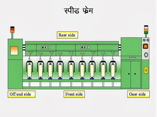
SIMPLEX (ROVING) FRAME
Simplex is the intermediate machine between draw frame and the ring frame. The purpose of the roving frame is to produce out of the draw frame sliver a well prepared roving of required as well as the prepare bobbin for the ring frame .

OBJECTIVES OF ROVING FRAME
  1. To draft the material to the required linear density.
  2. To insert minimum required level of twist.
  3. To produce a suitable package for the next process.
  4. To reduce the thickness of the sliver.

Technical Data:
  • Model: „„„„„„„„„„„„„„„„„„,LF1400 &LF1400A
  • Manufacturer:„„„„„„„„„„„„„ LMW
  • Year: „„„„„„„„„„„„„„„„„„„,1994 
  • Total no of spindles „„„„„„„„„120 
  • Drafting system „„„„„„„„„„„„3/3&4/4 drafting system
  • Spacer size „„„„„„„„„„„„„„„3.5to11mm
  • Bottom apron size „„„„„„„„„„76*40*1.0mm
  • Bottom roll dia „„„„„„„„„„„„,27-30mm
  • Top apron size „„„„„„„„„„„„,38.5*41.5*1.0mm
  • Cradle „„„„„„„„„„„„„„„„„„,31mm
  • Rubber cots „„„„„„„„„„„„„„29mm
  • Roller gauge „„„„„„„„„„„„„„45/58-45/68 
  • Saddle gauge „„„„„„„„„„„„„,51/56-51/66 
RING FRAME:
Ring spinning is the last state of conversion of fibre to yarn completely. Ring frame is the last machine in the spinning section.

OBJECTIVES OF RING FRAME

It performs mainly two operations:
  • To convert roving into yarn of required count.
  • To wind yarn on the cop.
Flowchart of Material:
KTTM (RXI 240)
  • Manufacturer: KTTM
  • Model: RXI-240 
  • Year: 1994 
  • Total no. of machines: 23 
  • No of spindles per machine: 864 
  • Spindle speed: 20000 rpm (max)
LAKSHMI-RIETER(G5/1)
  • Manufacturer: LAKSHMI-RIETER Model: G 5/1 
  • Year: 1994 
  • Total no. of machines: 25 
  • No of spindles per machine: 864 
Table:
COUNT
BLEND
ROVING
HANK
D.C.
B.DR
TC
TPI
T.M.
SPACER
2/40sPCCW
65/35
1.05
45
1.25
39
23.4
3.7
2.8mm
40sPCCH
52/48
1.05
46
1.25
51
21.9
3.46
2.8mm
40sPCCW
35/65
1.2
51
1.25
43
25.95
4.1
2.5mm
18sVISCOSE

1.7
57
1.25
44
14.05
3.31
3.5mm
40sPCCH
40/60
1.05
45
1.25
49
22.76
3.6
2.8mm